Curved concrete is by far stronger than flat concrete. The egg is one of nature’s strongest objects. Dome buildings share that attribute.
The Radius of Curvature is a number that is used to determine the “flatness” of a dome. In essence, the radius of curvature tells us how curved a curve is (Figure 1). The larger the dome, the less curve, the flatter the concrete.
If any three points are chosen on an arc, the center of the sphere that would rotate through the arc can then be determined (Figure 2). The sphere would have an edge along the arc.
When an oblate ellipse is built (Figure 3), the radius of the curvature of the base could be fairly small. As we go up over the dome, it flattens out more and more. The radius of curvature of an oblate ellipse reaches its maximum at the very top of the dome. In other words, the flatter the dome or section of the dome, the longer the radius of curvature. (Note: the footprint is round.)
Figure 4 illustrates the changing radius of curvature of the oblate ellipse. Notice that at the base the radius of curvature, R1, is the smallest. Following the curvature of the dome toward the apex, it is easily seen that the radius, R2, is larger, and R3 is larger still. Finally, at the very top of the dome, the radius, R4, is at its maximum and is much larger than R1.
A dome draws much of its strength from being curved in two dimensions. The sharper the curve, the stronger it is, much like the fender on an automobile. The fender has significant curvature to it, so if a child stands on the fender, it generally doesn’t have any problem. On the other hand, the hood of a car is pretty flat — it has a long radius of curvature versus the short radius of curvature for the fender. Therefore, you will find that in order to take a load, the hood has to have additional stiffening braces underneath it. We will call those stiffening braces ribs.
Since the dome becomes flatter as the radius of curvature gets larger, the concrete must be thicker for the dome to maintain its strength. Sometimes the radius of curvature becomes large enough that the dome becomes extremely flat — so flat that increasing the concrete thickness adds too much weight. So, a better way of maintaining the strength of the dome than merely adding more inches of concrete must be introduced.
The answer is ribs. The ribs allow us to make a deep section, an apparent thickness without adding a lot of weight. The pictures shown (Figures 5 and 6) are of a severely oblate ellipse. The top twenty feet are almost perfectly flat.
In order to prevent buckling in the flattened area at the top of the dome, ribs were used (Figure 7).
Thicker concrete could have been used, in this case, and been just fine, but the ribs were used to demonstrate their strengthening properties and benefits. The ribs take a little more time to form and put in place, but the benefits are great. They are made of rebar and wire mesh and sprayed with concrete. The concrete is only 2 1/2 inches thick between the ribs, which is more than enough to span the distance between the ribs. The ribs are approximately twelve inches deep; this gives a tremendous amount of strength to that area of the dome. As shown in Figure 7, the ribs do not have to extend down into the lower part of the shell.
As we build larger domes, we will need to use larger ribs. By using the larger ribs, we can eliminate much of the thickness of the shell, and therefore much of the weight of the shell (Figure 8). The ribs are another arrow in our quiver of options that we have in constructing domes.
June 18, 2009
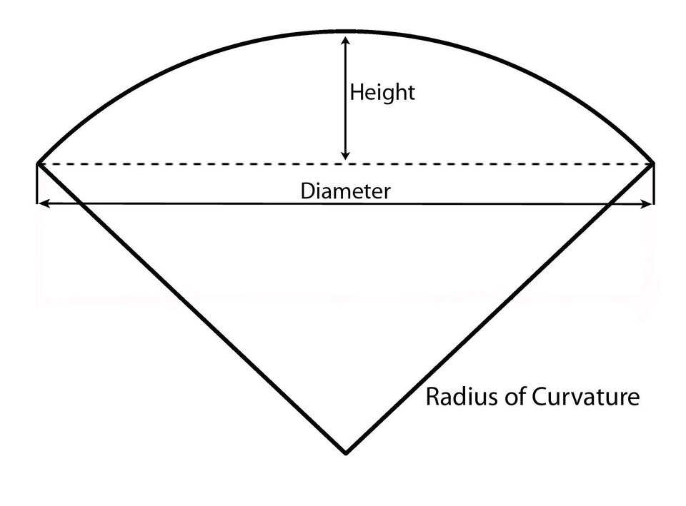
Figure 2 — The radius of curvature of a dome.
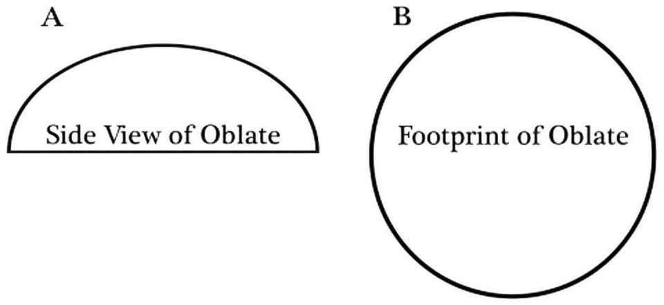
Figure 3 — The side view and footprint of an oblate ellipse.
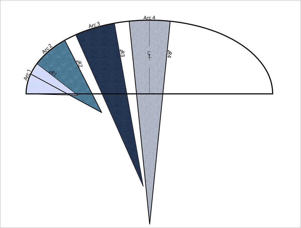
Figure 4 — The radii of the oblate ellipse ranging from smallest at the edge (R1) to largest at the top of the dome (R4).
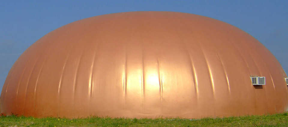
Figure 5 — Side view of oblate ellipse at Monolithic.
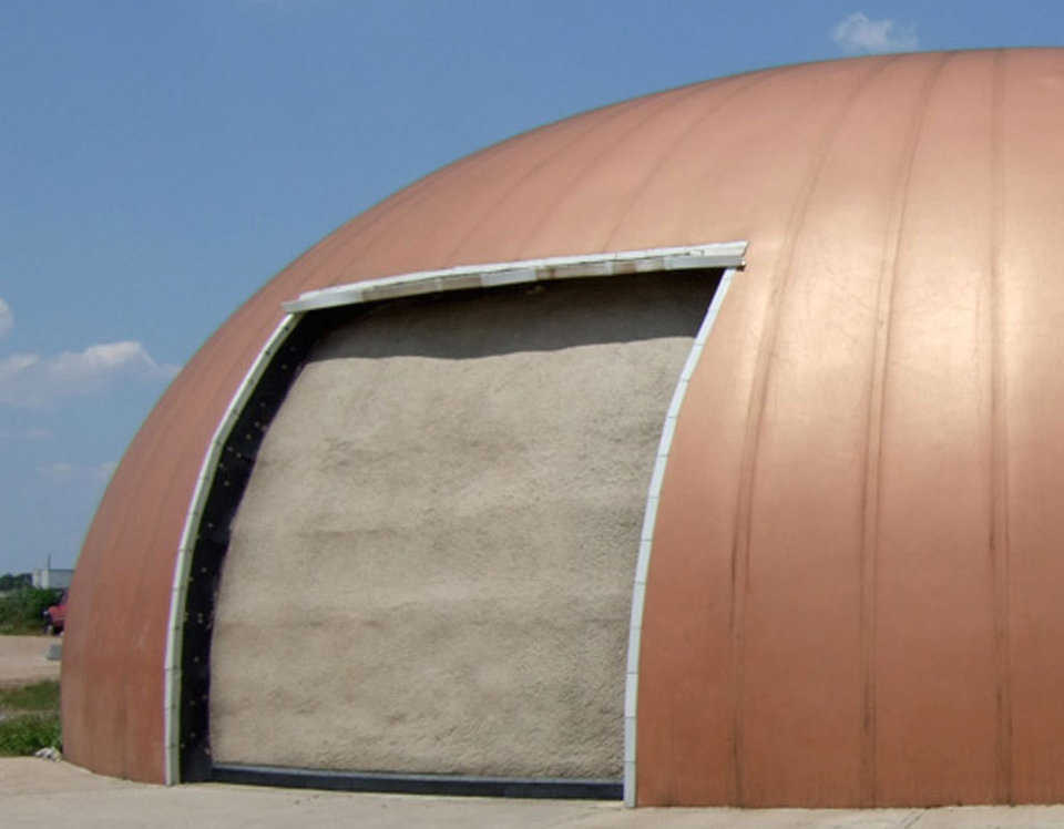
Figure 6 — Oblate ellipse with hanger door at Monolithic.
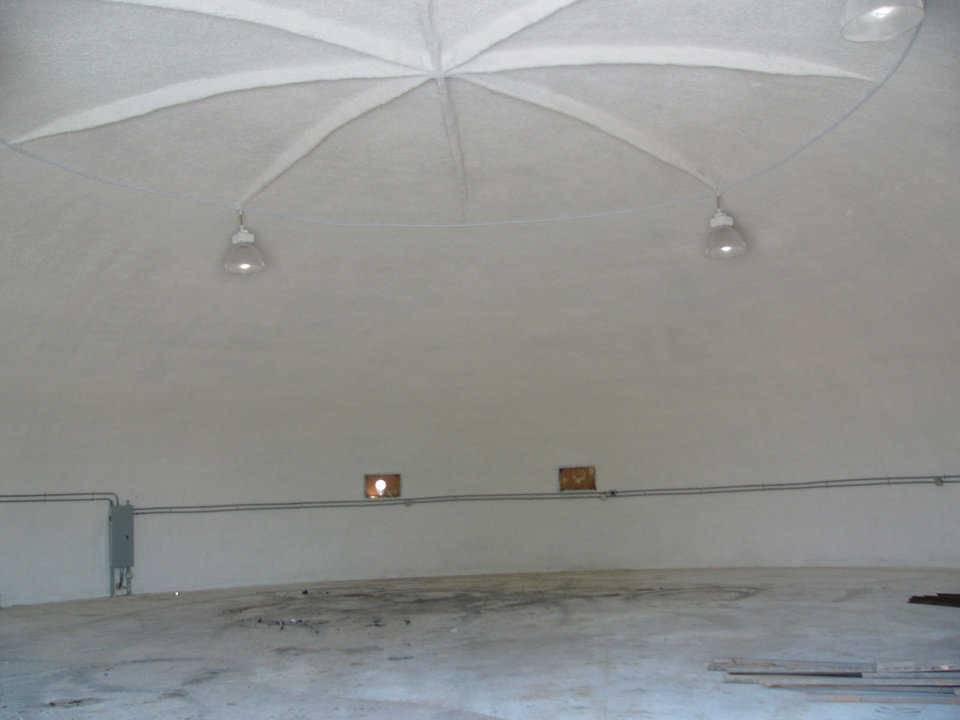
Figure 7 — Ribs strengthening top of oblate ellipse dome at Monolithic.
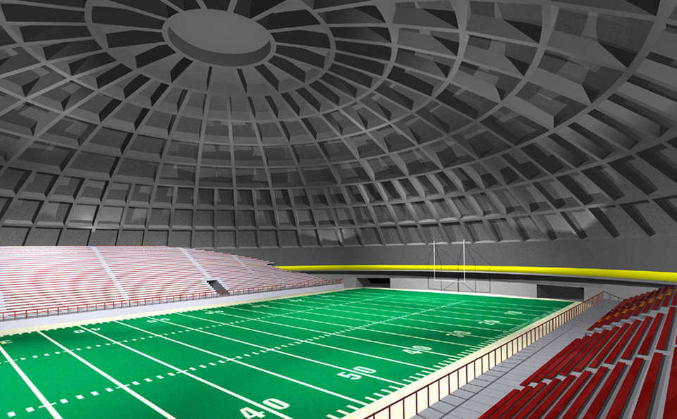
Figure 8 — A crenoshpere strengthened by ribs.
